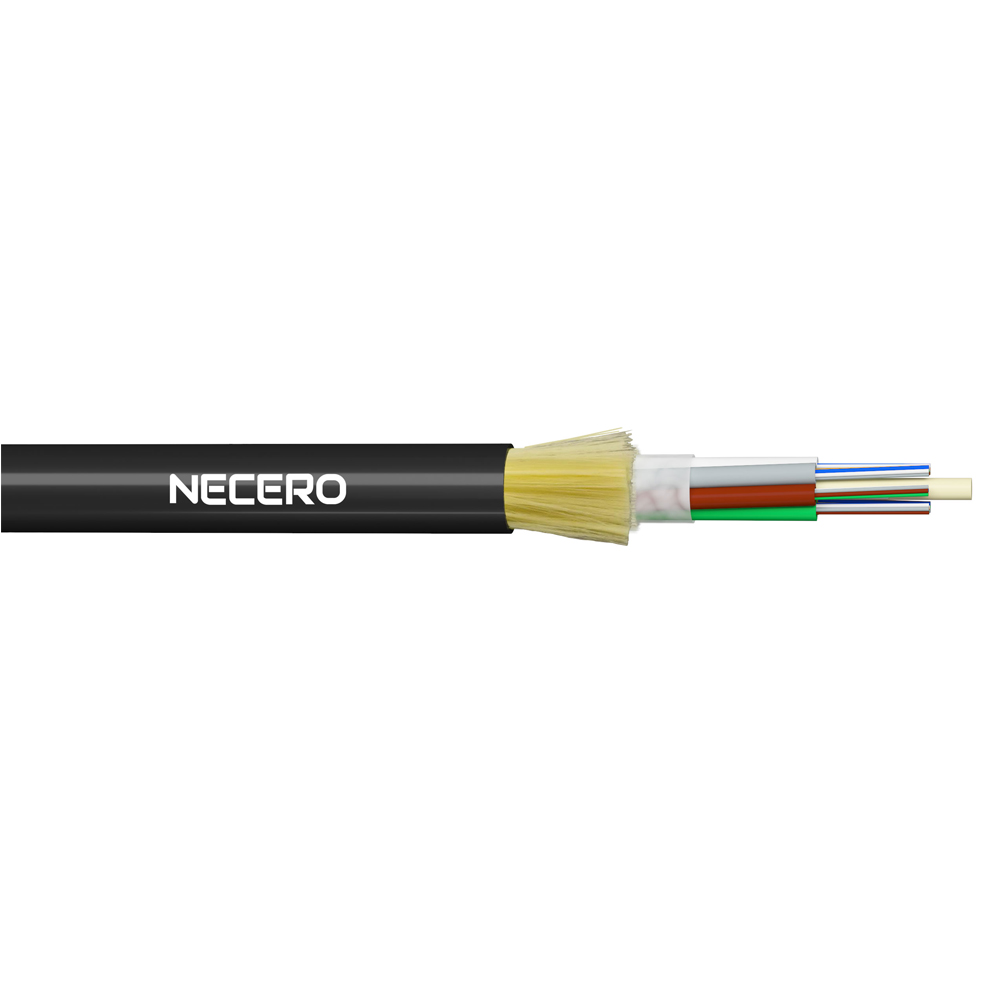
ADSS CABLE
ADSS Cable

- Description of the product


ADSS cable adopts the twisted structure of loose sleeve layer, 250 μm optical fiber is inserted into the loose tube made of high modulus materials, and the loose tube is filled with waterproof compounds. The loose tube ( and filling rope ) is twisted around the non-metallic center reinforcing core ( FRP ) to synthesize a compact cable core. The gap of the cable core is filled with a water-blocking yarn and a water-blocking belt longitudinally wrapped by the cable core, and then the aramid fiber that plays a reinforcing role is twisted. Finally, the polyethylene ( PE ) outer sheath or the electric mark ( AT ) outer sheath is extruded.

· Continuous electrical erection
· Superior resistance to electric marks with AT sheath
· Light weight, small cable diameter, reduced ice, wind impact and load on tower, support
· Excellent tensile and temperature properties
· Life expectancy up to 30 years
The design of ADSS cable takes full account of the actual situation of power lines and is suitable for different grades of high voltage transmission lines. Polyethylene ( PE ) sheath can be used for 10 kV and 35 kV power lines. For 110 kV and 220 kV power lines, the optical cable hanging point must be determined by calculating the electric field strength distribution and the electric mark ( AT ) outer sheath must be adopted. At the same time, the amount of aramid fiber and the perfect stranding process were carefully designed to meet the application requirements of different spans.

The ADSS cable follows the IEEE P 1222 technical standard, and meets the IEC 60794-1 standard and DLT 788-2016 standard.

G.652
G.655
50/125μm
62.5/125μm
Attenuation
(+20℃)@850nm
≤3.0 dB/km
≤3.0 dB/km
@1300nm
≤1.0 dB/km
≤1.0 dB/km
@1310nm
≤0.00 dB/km
≤0.00dB/km
@1550nm
≤0.00 dB/km
≤0.00dB/km
Bandwidth(Class A)
@850nm
≥500 MHz·km
≥200 MHz·km
@1300nm
≥500 MHz·km
≥500 MHz·km
Numerical aperture
0.200±0.015NA
0.275±0.015NA
Cable Cutoff Wavelength
≤1260nm
≤1480nm

Cable Diameter
mm
Cable Weight
kg/kmRecommend maximum working tension
kN
Maximum allowable working tension
kN
breaking tenacity
kN
Section area of tensile components
mm2
modulus of elasticity
kN/ mm2
thermal expansion coefficient ×10-6 /k
PE sheath
AT sheath
9.8
121
130
1.5
4
10
4.6
7.6
1.8
10.2
129
138
2.1
5
14
6.9
8.1
1.4
13.1
132
143
2.8
7
19
9.97
9.13
1.2
15.6
189
207
3.8
9
26
14.2
11.2
1.0


